An electrical power transmission system is a vital infrastructure that facilitates the transfer of electrical energy from power generation sources to distribution networks, which then deliver electricity to homes, businesses, and industries. It involves the use of high-voltage transmission lines and associated equipment to efficiently transport large amounts of electricity over long distances. Here's an overview along with a simplified single-line diagram:
Components of Electrical Power Transmission System:
Generating Stations: These facilities generate electricity using various sources such as coal, natural gas, hydroelectric, nuclear, and renewable sources like solar and wind.
Step-Up Transformers: The generated electricity is initially at a low voltage. Step-up transformers increase the voltage to suitable levels for efficient long-distance transmission.
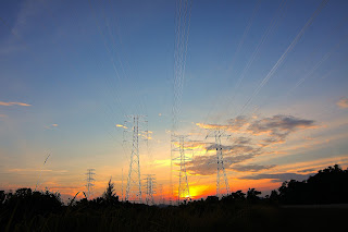
Transmission Lines: High-voltage transmission lines carry the electricity over long distances. These lines are supported by towers and pylons.
Substations: Substations are intermediate points along the transmission route. They contain equipment for voltage conversion, switching, and protection. Step-down transformers reduce the voltage for distribution.
Switching Equipment: Circuit breakers and switches are used to control and isolate sections of the transmission network for maintenance and safety.
Reactive Power Compensation: Equipment such as capacitors and reactors are used to manage reactive power and improve the efficiency of the transmission system.
Protection Systems: Protection relays monitor the system for faults and abnormalities, isolating faulty sections to prevent widespread outages.
Control Centers: System operators monitor and control the transmission system from central control centers, managing load distribution and responding to emergencies.
Earthing and Grounding: Proper grounding and earthing systems protect equipment and personnel from electrical faults and lightning strikes.
Single-Line Diagram of Electrical Power Transmission System:
   Generating Station
      |
      |
      V
   Step-Up Transformer
      |
      |
      V
  Transmission Lines (High Voltage)
      |
      |
      V
      Substation
      / \
     /   \
    /     \
 Step-Down Step-Down
 Transformer Transformer
    |        |
    |        |
    V        V
  Distribution Distribution
  Networks   Networks
    |        |
    |        |
Homes,    Businesses,
Industries etc.
In this simplified single-line diagram:
- Electricity generated at the power station is stepped up using a transformer for efficient transmission.
- The high-voltage transmission lines transport electricity over long distances.
- Substations along the route house equipment for voltage transformation and distribution.
- Step-down transformers reduce the voltage before sending electricity to distribution networks.
- The distribution networks deliver electricity to end-users, such as homes, businesses, and industries.
The electrical power transmission system plays a crucial role in ensuring a reliable and stable supply of electricity across regions. It enables the efficient movement of large amounts of energy, contributing to the functioning of modern societies and economies.