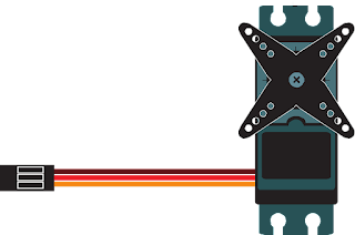
Classifications of servo motor
Based on applications, there are various types of servo motors. They are: AC servo motor, and DC servo motor. A servo motor can be evaluated based on three factors. They are: type of current (whether it is DC or AC), motor brushes (commutation) and motor rotation (whether it is synchronous or asynchronous). Let’s discuss the first servo consideration. AC or DC consideration is the most basic classification of a motor based on the type of current it will use.
DC and AC motors can be differentiated based on their ability to regulate the speed. At a constant load, the speed in a DC motor is directly proportional to the supply voltage with a constant load. On the other hand, speed in an AC motor is determined by the number of magnetic poles and the applied voltage's frequency. AC motors can resist high current. They are broadly used as robots where high accuracy and recurrences are required. For example, we can mention say in-line manufacturing and other industrial applications. A DC Servo Motor can be brushed or brush less. In electronically, it is brush less. Operation of Motors with brush are quite easy and comparatively cheap. On the other hand, brush less motors provide high efficiency with little noisy and are more dependable.
In order to reverse the current direction periodically between the rotor and the drive circuit, a rotary electrical switch is used which is known as a commutator. It contains a cylinder having multiple metal contact segments on the rotor. Multiple electrical contacts known as “brushes” built with a soft conductive material like carbon press against the commutator, creating a sliding contact with commutator's segments as it rotates. Most of servo motors are AC brush less. In order to reduce the cost and for easy operation, brushed permanent magnet motors work as servo motors sometimes. Permanent magnet DC motor is an example of typical type of brushed DC motor. An encoder or hall effect sensor is used in brush less DC motors for communicating electronically.
Rotating speed of the rotor is as like as the speed as the rotating magnetic field of the stator in a synchronous motor. On the other hand, in an asynchronous motor, also known as an induction motor, the rotor rotates with a lesser speed than rotating magnetic field of the stator. By changing the frequency and the number of poles, it's speed can be regulated.
How servo motor works?
DC servo motor operates based on four core components like a DC motor, a gear assembly, a control circuit and a position sensing device. By applying voltage, DC motor's required speed can be achieved. Voltage is produced by a potentiometer for controlling the speed of the motor. A control pulse can also be used in some circuits for producing DC reference voltage which is applied to a pulse width voltage converter. In order to generate the pulses in terms of duty cycles for getting accurate digital control, a PLC (Programmable Logic Controller) is used. A voltage corresponding to the absolute angle of the motor shaft through the gear mechanism can be produced by using the feedback signal sensor which is usually a potentiometer. Feedback voltage value is applied to the amplifier which compares the voltage produced from the current position of the motor resulting from the potentiometer feedback and to the required motor's position causing an error either of a positive or negative voltage. Error voltage is applied to motor's armature which is amplified by the amplifier for energizing the armature. Until error becomes zero, the motor rotates. The armature voltage reverses when the error is negative. As a result, the armature rotates in the opposite direction.
Two core components such as stator and rotor exist in asynchronous AC servo motor. There are two components exist in the stator. They are: cylindrical frame and stator core. Around the stator core, the armature coil is wound and the coil is connected to a lead wire through which current is supplied to the motor.
In brush less servo motor, a permanent magnet exists in the rotor which is induced by electromagnetism.Synchronous form is achieved when the rotor is synchronized with the energized field of the stator. If the stator field is de-energized, the rotor stops rotating. As there is no rotor current in these motors, the efficiency of these motors are very high. In order to give feedback to the servo motor controller, an encoder is added to the rotor.
Stator core, lead wire, armature winding, rotor with shaft and the rotor core winding exist in the asynchronous or induction AC servo motor. The rotor or squirrel cage is available in most induction motors. After getting AC supply, an alternating flux field is generated around the stator winding which resolves with synchronous speed.This revolving flux is also known as a rotating magnetic field (RMF).
According to electromagnetic induction law of Faraday, an induced electromagnetic force in the rotor conductors is produced due to the relative speed between stator rotating magnetic field and rotor conductors. An alternating flux field around the rotor is generated by the induced current in the rotor known as rotor flux which lags behind the stator flux.
The rotor velocity is related between the rotating stator flux field and the rotor rotates in the same direction as that of the stator flux. In this case, asynchronous type is originated as the rotor speed can't synchronize with the stator flux speed.
