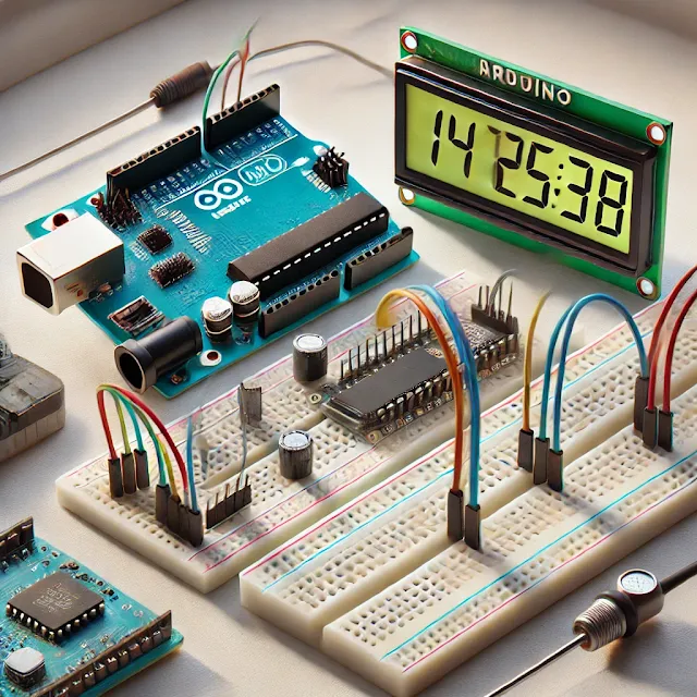
Required Components:
- Arduino Board (e.g., Arduino Uno or Nano): This will be the brain of your digital clock.
- RTC Module (DS3231 or DS1307): A real-time clock module to maintain accurate time even when the Arduino is powered off.
- 16x2 LCD Display: To display the time.
- Potentiometer (10K): To adjust the contrast of the LCD.
- Breadboard and Jumper Wires: For connecting the components.
- Resistors (220 ohms): For current limiting, used in conjunction with the LCD backlight.
- Push buttons: Optional, for setting the time manually if desired.
- Power Supply (USB or External): To power the Arduino.
Circuit Design
Step 1: Connecting the RTC Module
The RTC module is used to keep track of the time. It’s accurate and has a built-in battery to maintain time even when the system is powered off.
- VCC pin of the RTC module to 5V on the Arduino.
- GND pin of the RTC module to GND on the Arduino.
- SCL pin of the RTC module to the A5 (for Uno/Nano) on the Arduino.
- SDA pin of the RTC module to the A4 (for Uno/Nano) on the Arduino.
The RTC uses the I2C protocol, which requires two pins (SDA and SCL).
Step 2: Connecting the LCD Display
The 16x2 LCD will be used to display the current time. The LCD is interfaced with the Arduino in 4-bit mode to reduce the number of required pins.
- VSS pin of the LCD to GND on the Arduino.
- VDD pin of the LCD to 5V on the Arduino.
- V0 pin of the LCD to the middle pin of the potentiometer (contrast control).
- RS pin of the LCD to D7 on the Arduino.
- RW pin of the LCD to GND on the Arduino (for write operations).
- E pin of the LCD to D8 on the Arduino.
- D4-D7 pins of the LCD to D9-D12 on the Arduino (for data transfer).
- A (Anode) pin of the LCD to 5V through a 220-ohm resistor (for backlight).
- K (Cathode) pin of the LCD to GND.
Step 3: Setting Up the Potentiometer
The potentiometer is used to control the contrast of the LCD.
- Connect the two outer pins of the potentiometer to 5V and GND.
- Connect the middle pin to the V0 pin of the LCD.
Step 4: Wiring Push Buttons (Optional)
If you want to manually adjust the time, you can add push buttons for setting hours and minutes. Connect these buttons to available digital pins on the Arduino (for example, D2 for hours and D3 for minutes) with pull-down resistors.
Programming the Arduino
Step 1: Installing Required Libraries
To interface with the RTC module and the LCD, you will need the following libraries:
- RTClib: For communicating with the RTC module.
- LiquidCrystal: For controlling the LCD.
You can install these libraries from the Arduino Library Manager.
Step 2: Writing the Code
Here’s a sample code that initializes the RTC, reads the time, and displays it on the LCD:
#include <Wire.h>
#include <RTClib.h>
#include <LiquidCrystal.h>
// Initialize the RTC and LCD
RTC_DS3231 rtc;
LiquidCrystal lcd(7, 8, 9, 10, 11, 12);
void setup() {
// Start the serial communication
Serial.begin(9600);
// Initialize the LCD and set up the dimensions (16x2)
lcd.begin(16, 2);
lcd.print("Initializing...");
// Initialize the RTC
if (!rtc.begin()) {
Serial.println("Couldn't find RTC");
lcd.clear();
lcd.print("RTC Error!");
while (1);
}
if (rtc.lostPower()) {
Serial.println("RTC lost power, setting time!");
rtc.adjust(DateTime(F(__DATE__), F(__TIME__)));
}
// Clear the LCD screen
lcd.clear();
}
void loop() {
// Get the current time from the RTC
DateTime now = rtc.now();
// Display the time in HH:MM:SS format
lcd.setCursor(0, 0);
lcd.print("Time: ");
lcd.print(now.hour(), DEC);
lcd.print(':');
lcd.print(now.minute(), DEC);
lcd.print(':');
lcd.print(now.second(), DEC);
delay(1000); // Update every second
}
Step 3: Uploading the Code
- Connect your Arduino to the computer and upload the code using the Arduino IDE.
- Once the code is uploaded, the clock should start running, and you’ll see the current time displayed on the LCD.
Technical Specifications
2. RTC Module: DS3231/DS1307, provides accurate timekeeping with battery backup to keep time even when power is off.
- Accuracy: ±2ppm from 0°C to +40°C.
- Battery: CR2032, capable of keeping time for years without external power.
- Operating voltage: 4.7V – 5.3V.
- Display: 16 characters and 2 lines.
- Interface: 4-bit/8-bit parallel.
4. Potentiometer: Used to adjust the contrast of the LCD.
5.Push Buttons (Optional): For setting the time manually (optional).
- Normally open (NO) type buttons.
Analysis and Considerations
- Power Consumption: The Arduino and the attached components operate at 5V, with relatively low power consumption, making this project suitable for portable or low-power applications.
- Time Accuracy: The DS3231 RTC is highly accurate, with an error margin of less than 2 parts per million. This ensures that the clock will not drift significantly over time.
- Expandability: You can add additional features to the clock, such as alarms, a temperature display, or even a date display by modifying the code and adding extra components.
Troubleshooting
- Time Resetting: If the clock resets every time you power off the Arduino, check if the RTC module’s battery is correctly installed.
- Incorrect Time: If the time displayed is incorrect, you may need to adjust the RTC time in the code or reset it using the
rtc.adjust()function. - Display Issues: If the LCD display is garbled or not displaying anything, adjust the potentiometer to set the correct contrast level.
Conclusion
Building a digital clock using Arduino is a rewarding project that combines both hardware and software skills. With the right components and code, you can create an accurate and efficient clock that maintains time even when powered off. By following the steps and code outlined in this guide, you can successfully build and expand upon your own digital clock. Whether for learning or practical use, this project is a great way to dive into electronics and Arduino programming.


